ContextCapture Automatically transforms photos into a 3D model, this means that the quality of the input data set has a direct impact on the quality of the 3D model that will be generated.
In this page you will find useful information on how to acquire the photos in order to obtain an optimal result with ContextCapture.
- How to set your device?
- Limitations on use
- How to capture an object?
- How to capture a body or face?
- How to capture facades and buildings?
- How to capture an inside?
- Acquisition configuration for UAS, UAV and drones
- Acquisition of aerial data using multi-camera systems
- Example
- Conclusion
How to set your device?
Different types of cameras can be used to capture an input data set for ContextCapture, from smartphone to the latest digital reflex. The resulting quality of 3D models will depend on the quality of the input photos and their spatial configuration.
To achieve the best results in ContextCapture, us Recommended :
- A constant focus when acquiring: zoom in « with your feet» ;
- Constant and homogeneous lighting.
We advise you avoid :
- The blurred photos: using suitable parameters and possibly a tripod in low-light conditions;
- Flash use;
- Optical stabilization.
You must ban at any cost:
- Digital zooms;
- Any scaling/rotation manipulation on input photos (also disable the auto-rotation mode of your camera).
For video acquisition, the following formats are recommended:
- Audio Video Interleave (AVI)
- MPEG-1/MPEG-2 (MPG)
- MPEG-4 (MP4)
- Windows Media Video (WMV)
- Quicktime (MOV)
For more information, refer to the User Guide ContextCapture : Preparing the imagery dataset.
Limitations on use
- Enough photos must be taken to cover the entire object to be rebuilt. Each point of the scene must be captured in at least 2 adjacent photos.
- The transparent or shiny parts cannot be properly rebuilt: glass, water, etc.
- Parts of the object with a uniform appearance cannot be rebuilt: smooth walls without texture, etc.
- Photos of the same part must not be taken from too similar or too different points of view.
How to capture an object?
The capture of an object is one of the simplest cases. Therefore, we recommend that you start with this for your learning of ContextCapture. Despite this, it is necessary to acquire a little knowledge and practice to ensure that the result is satisfactory. Remember that each part you want to rebuild must be visible in at least 2 different photos.
An easy way to meet this requirement will be to rotate around the small step object (make sure you have a minimum of 60% overlap and a maximum angle difference of 15° between consecutive photos) – See « Figure 1 ». Generally, you will want a consistent resolution. To do this, try to keep the device at the same distance from the object throughout the acquisition.
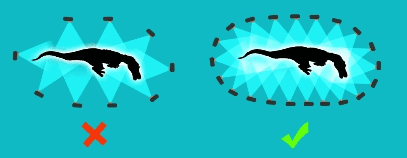
FIGURE 1: ACQUISITION OF AN OBJECT
If you want more details in some parts of the 3D model, gradually take photos closer and closer to the object. Be aware that having photo resolutions that are too different can lead to failure during aerotriangulation. For this reason, it is recommended that intermediate photos be used to link those taken at a distance closer to and beyond (Figure 2).
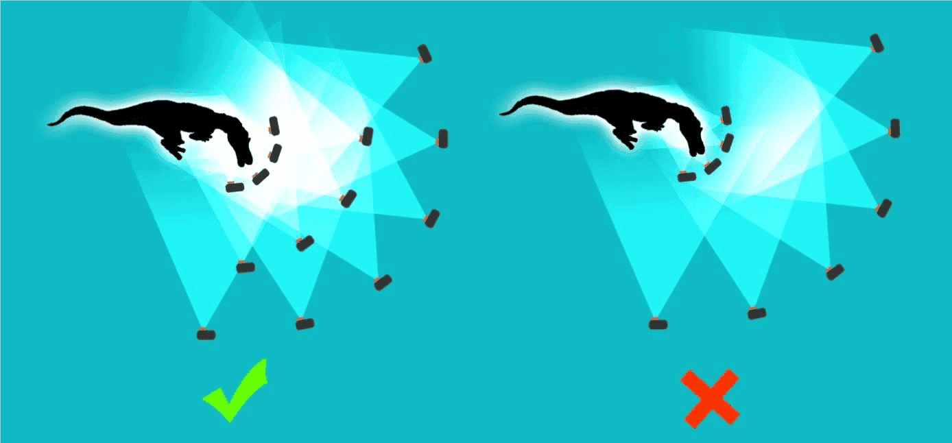
FIGURE 2: CAPTURE A PURPOSE WITH MISCELLANEOUS DETAIL LEVEL
To make sure you have all the details of the object, turn around the object at different heights. This will provide the least visible areas (Figure 3).
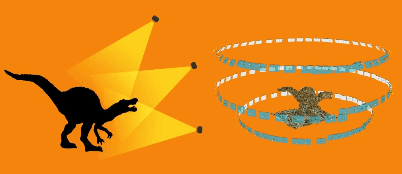
FIGURE 3: TOURING AUTHORITY OF A DIFFERENT PURPOSE
If the object has little texture, aerotriangulation may fail due to an insufficient number of points of interest. To remedy this problem, we recommend placing the object on a very textured surface (Figure 4): a journal for example.
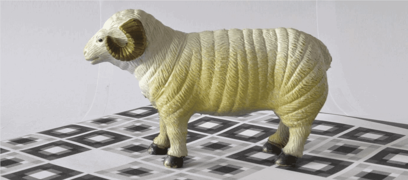
FIGURE 4: PLACE THE SUBJECT ON A TEXTURED SURFACE
Capturing an object with a background is sometimes delicate, because in photogrammetry, the subject must remain motionless throughout the acquisition. If you rotate the object, the background will not be compatible with the rest of the data set, resulting in a failure.
There are several ways to deal with this difficulty:
- Take photos of the object from all necessary points of view and hide the background manually in all photos with third-party image editing software (this process can be tedious).
- Creation of a « studio» (Figure 5): This will consist of a completely untextured location. For example, use a white support on a uniform white background and return the object instead of turning around. You will then be able to capture part of the object without being embarrassed by the background (Figure 5). It will also be important to have uniform, shadowless lighting.
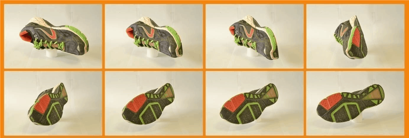
FIGURE 5: METHOD OF THE TOURNING PLATEL
How to capture a body or face?
Capture a human or animal face or body to create a 3D model can be very difficult. Indeed, the subject must remain perfectly motionless for the entire period of acquisition, which is practically impossible to achieve with a living being.
This is why professionals generally use RIGs (rigid camera systems). These systems are composed of several synchronised cameras to take photos simultaneously. The acquisition of all the photos is then instantaneous, thus avoiding the parasitic movements of the subject. The camera configuration must follow the same principles as for scanning the object. The big difference is that the increase in the number of photos means the increase in the number of physical cameras, with an obvious impact on the cost of the system.
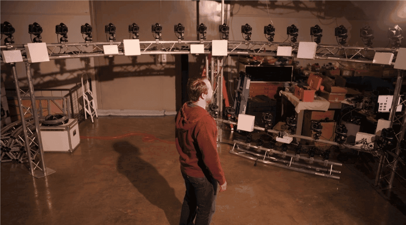
RIG – Rigid camera system
If you cannot afford a rigid camera system and you have the need to grab the bodies or faces with a single camera, it is recommended to reduce the acquisition time to a minimum as the chances of the subject's movements increase over time. The hair is also very complicated to model correctly, so be very careful when taking a shot and not forget to take photos from the top of the head.
You should also try to reduce the amount of background of your photos and try to get as much as possible the main topic (Figure 6). This also applies to all types of scenes.
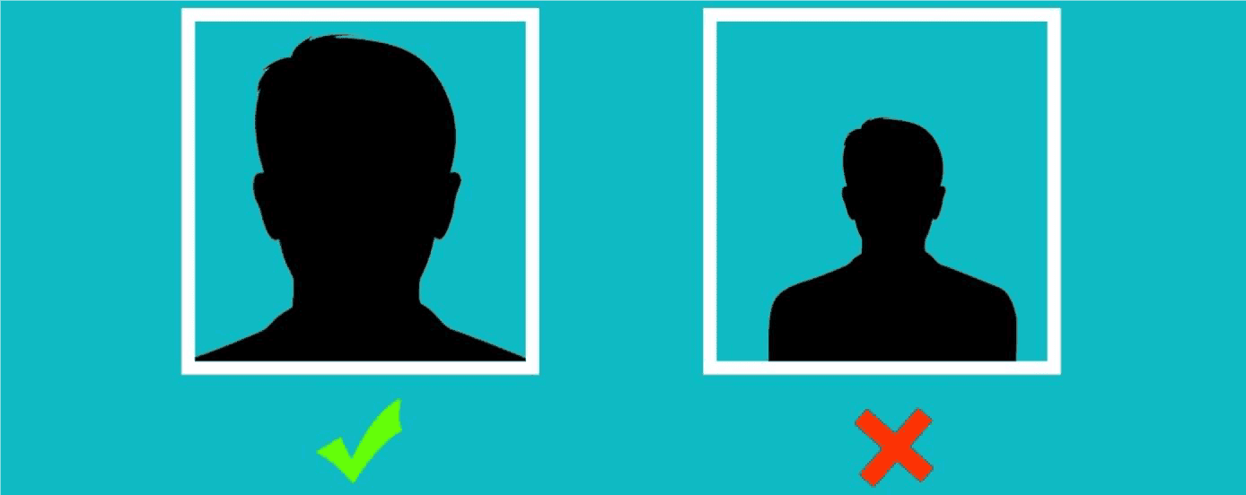
FIGURE 6: VISIT TO BE FUTURELY FUTURE
How to capture facades and buildings?
Certain rules must be respected in order to ensure a good acquisition:
- Follow a structured shooting order to avoid oblivion;
- Photograph at least 3 times the same part of different views;
- Limit the angle between two consecutive photos to a maximum of 15°.
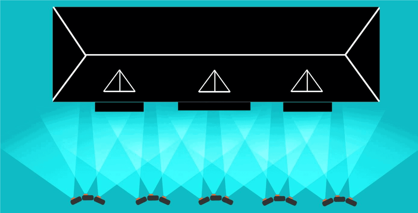
FIGURE 7
If you want to rebuild the entire building and not just a single façade, make sure you respect the maximum angle of 15° between two consecutive images by turning around the corner (Figure 8). This way you will help ContextCapture connect the different sides of the building.
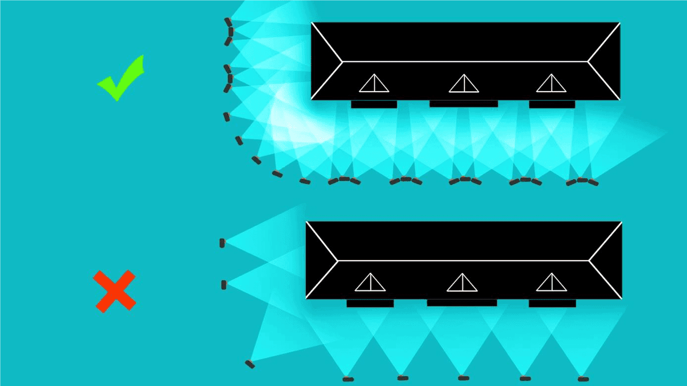
FIGURE 8: TOURING TO THE COIN OF A BUILDING
If the building cannot be photographed in full height due to a lack of distance and/or because the building is too large, you will have to reproduce the diagram in Figure 8 at several heights. This requires a lift, a pole or a UAS/UAV[1]/drone. Otherwise, just take successive photos from bottom to top, respecting the 60% recovery rule. In this case, it is possible that ContextCapture could lack information to properly rebuild the upper parts and roof.
When using a drone, we recommend turning around the building at different levels to limit hidden areas (Figure 9). In this case, you can complete your data set with aerial photographs on the ground.
Remember that reflective, bright or transparent surfaces can be difficult, if not impossible to reconstruct.
[1] UAS = Unmanned Aerial Systems – UAV = Unmanned Aircraft Vehicle
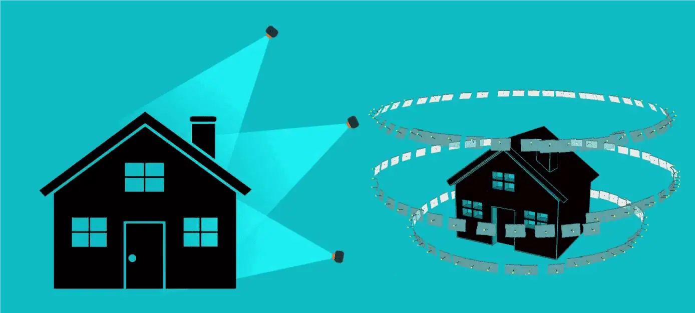
FIGURE 9: TOURING AUTHORITY OF A DIFFERENT HIGHER BUILDING
How to capture an inside?
Rebuilding interiors using photogrammetry is a difficult task. The short distance between the subject and the many objects creating masks greatly increases the number of photos needed to reconstruct the scene correctly.
Figure 10 shows the correct acquisition pattern for capturing interior scenes. To get the maximum distance from the scene, stand near the wall and photograph the opposite side of the room. A common mistake is to stand in the centre of the room and make panoramic shots.
It may be necessary to perform the process described in Figure 10 at different heights. If furniture or equipment are present in the room, you will need more photos (and perhaps on more different heights) to perform a correct modeling.
Another common problem is a lack of texture on the walls. This can lead to holes in the 3D model, or even failure during the aerotriangulation phase (see section « Limitations » ).
Use of a Fish-eye lens may be useful in cases where the distance from the scene (such as the interiors) is limited.
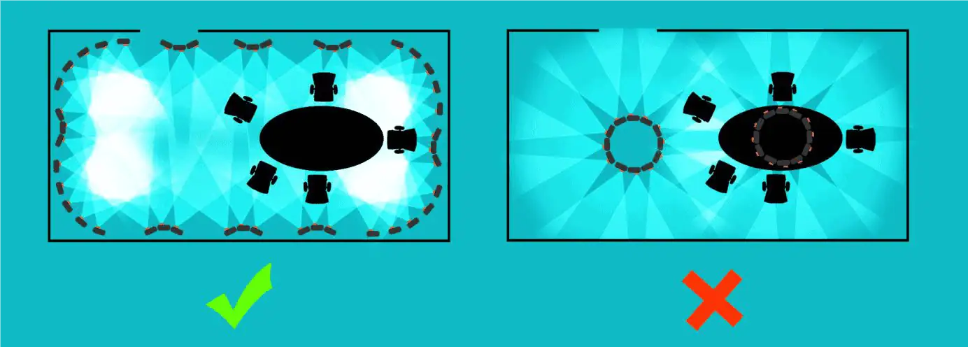
FIGURE 10: PROCESS FOR INTERNAL PRACTICE
Acquisition configuration for UAS, UAV and drones
The acquisition of data using tools such as UAS, UAV and drones (unmanned aerial system) can be used for a variety of purposes, such as: orthophotography, DSM production, inspection, single building modeling, or neighbourhood modelling (a city scale modelling will require more autonomous acquisition systems).
The acquisition configuration varies from one application to another and it will have to be adapted to achieve the best results in each application.
When precision is paramount, we recommend the use of quality lenses with a small distortion and preferably the choice of a camera with a fixed focal point and a large sensor.
For a given number of megapixels per photo, a camera with a larger sensor size will produce better quality photos. That being said, the choice of the camera is often determined by the maximum payload of the drone.
Accuracy of 3D models
To the extent that professional users of AUS, UAV and drones often have dedicated flight planning software (automatically creating the best flight plan for a given aircraft, lens and ground distance), it is interesting to know how to calculate the accuracy that can be expected.
Topographical surveys always include accuracy of results. The following formula will help you estimate the expected accuracy of the production of ContextCapture.
- Ls .........: the largest dimension of the sensor (mm)
- D The distance between the camera and the object (m)
- F ........ : the focal distance of the camera (mm)
- L ........ : the largest dimension of the photo (Px)
- R .................... : spatial ground resolution of photos (m/Px)
- P ....................: the space positioning accuracy of the tops of the 3D mesh.
Since Ls, f and L are generally fixed for a given aircraft, the only way to improve accuracy is to decrease flight height. This will also lead to taking more photos to cover the same area.
P is the relative precision of the 3D mesh. The absolute precision of your model will only make sense if it is georeferenced.
In ContextCapture, your model can be geo-referenced either by using the imported 3D positions of the photos (through EXIF tags or using an import file), or by adding control points (most spatial reference systems are supported).
The absolute accuracy will then depend on the relative accuracy of the 3D mesh and the accuracy of the control points (or 3D positions on the photos).
Ortho-photos and production of DSM
The production of ortho-photos and DSM does not necessarily require the acquisition of oblique views. Photos « nadiral[1] » with enough overlap are sufficient to perform the processing (many UAS, UAV or drone acquisition systems are not able to capture oblique images).
In such cases, it is recommended that an overlap of 80% be achieved in the direction of advancement and 60% overlap across the flight line for optimal acquisition (Figure 11).
[1] Nadiral = opposite of « Zenithal »
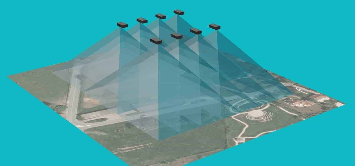
FIGURE 11: RECOVERY FOR PRODUCTION D
Positioning of ground control points, regularly distributed around the area of interest, is also recommended.
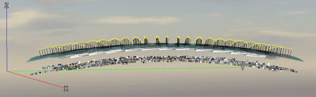
FIGURE 12: EFFECTS OF CURRENT EFFECTS IN REASON OF AMBIGUITED IN RADIAL DISTORSION
Problem known during self-calibration of radial distortion :
For acquisition configurations including photos in mode « nadiral » Only you can experience a curve effect after the aerotriangulation step (Figure 12). Acquisitions consisting of a straight line along a single axis on a fairly flat surface are likely to be critical.
This curvature effect is due to a critical configuration that leads to ambiguities when calculating radial distortion parameters. This « fault » is shared by all software based on « structure from motion » (SFM). For more details, this is described in the following research article: Changchang Wu, « Critical Configurations For Radial Distortion Self-Calibration », CVPR 2014.
How to solve or prevent this phenomenon from occurring :
The best way to avoid, is to perform a calibration of your camera before the flight.
In ContextCapture, it is possible to store the camera calibration in a « database of user devices » (right click on photogroup -> « Add camera model to database » / « Get camera model from database »).
Note that your camera settings may change over time (especially for non-metric cameras). Therefore, it is recommended to calibrate your camera as often as possible, and preferably just before the flight.
The path to implementing this solution is as follows:
- Before the flight, make about 20-30 photos around a very textured and geometrically complex object with the same camera properties as those used during the flight;
- Acquire your aerial acquisition;
- Perform the aerotriangulation of the 20-30 photos of your object (non-critical configuration) and add the calibration resulting from the device to the database as explained above;
You can now reuse this calibration in your project: right-click on the photogroup -> « Get camera model from database » to import your fitted camera model and present the AT. Do not forget to prevent the software from recalculating these parameters itself (Figure 13).
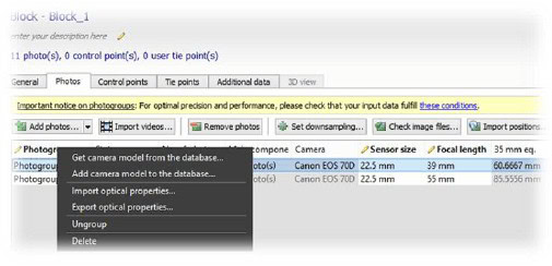
FIGURE 13: ADD A APPARATUS TO THE DATABASE
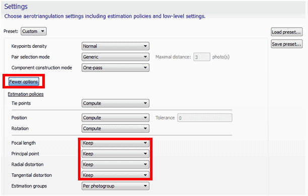
FIGURE 14 STORING OPTICAL PARAMETERS IMPORTED AT AEROTRIANGULATION
The second way to solve this curvature problem is to add additional points of view to your flight, on different axes or with different flight heights. However, this solution is not recommended.
Complete 3D modelling
Getting complete 3D models with UAS, UAV or drone can be quite complex and requires a large amount of photos, including nadiral and oblique. Since most of these devices are unable to charge more than one camera at a time, several flights are required with different orientations of the camera in order to collect all points of view.
We recommend that you read the section carefully: « Aerial multi-camera system dataset acquisition ».
Acquisition of aerial data using multi-camera systems
Generating large 3D models, such as those in a city, requires the acquisition of a large amount of data. This usually requires a multi-camera system that provides nadal and oblique photos in different directions: this limits the number of flights needed to cover the entire region.
This type of multi-camera system can be « homemade » or purchased from a company marketing its own acquisition systems: VisionMap, IGI, Microsoft Vexcel, Icaros, visual intelligence, TrackAir, etc.
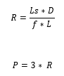
We recommend the following settings:
- 1 shooting in nadiral mode and 4 (or more) configuration in oblique configuration;
- 80% cover in the direction of flight and 60% side cover;
- Have the same approximate ground spatial resolution for nadiral shots as for obliques;
- The angle of oblique shots shall be less than 45° from the vertical.
If your scene includes high buildings and narrow streets, you have to choose a slightly lower angle (about 30° from the vertical). This will allow you to better grasp the streets and the bottom of the buildings, avoiding holes in the final model.
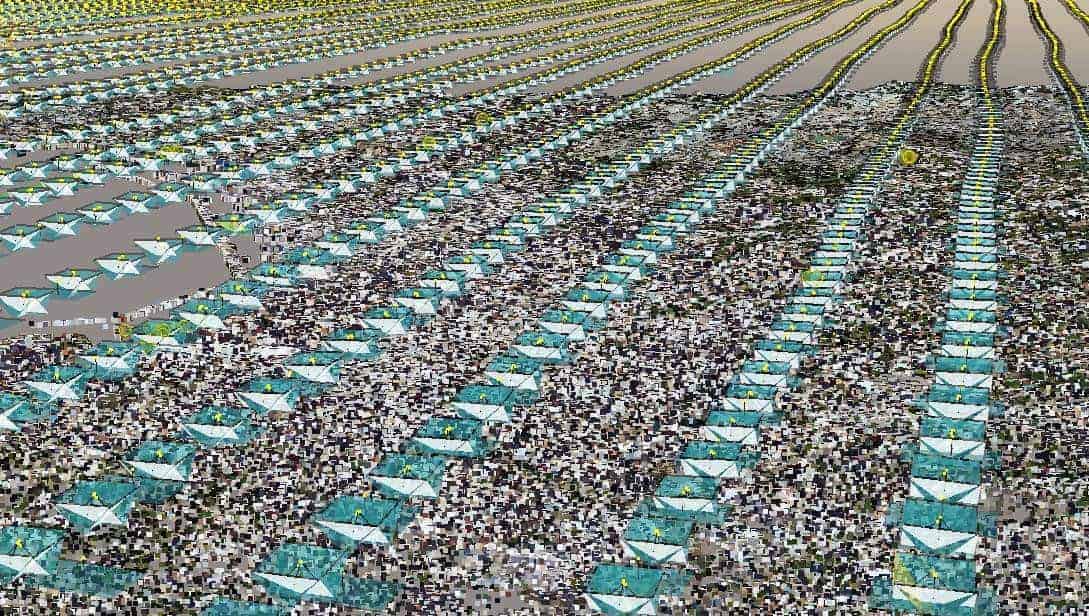
FIGURE 15 : ACQUISITION OF DATA IN MARSEILLE, FRANCE
The distance between flight lines and the shooting frequency will be determined by the flight height to ensure the required overlaps between photos (for a given aircraft).
Example
For this example, we will consider a camera system UltraCam Osprey of the Vexcel.
We will learn to calculate the following points:
- Flight height
- distance between flight lines
- shooting speed
- overlap
- ground resolution of oblique photos
The device consists of:
- 1 apparatus in nadiral mode
- Sensor size ............................: 70.044 x 45.084 mm
- Focal distance.........: 80 mm
- Size of the photos................... : 11674 x 7514 Px
- View angle: Vertical
- Orientation: Landscape (according to flight direction)
- 2 devices in oblique mode (front and rear)
- Sensor size ................................: 53.4 x 39.9 mm
- Focal distance.........: 120 mm
- Size of the photos........ : 8900 x 6650 Px
- View angle: ? = 45° from vertical
- Orientation: Landscape
- 2 devices in oblique mode (left and right)
- Sensor size ................................: 53.4 x 39.9 mm
- Focal distance.........: 120 mm
- Size of the photos........ : 8900 x 6650 Px
- View angle: ? = 45° from vertical
- Orientation....: Portrait
Consider the following values:
- Ls ..........: larger sensor size (mm)
- ls ..........: smaller sensor dimension (mm)
- D .........: distance between camera and object (m)
- H .........: flight height (m)
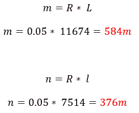
- m ......... : length of the largest side of the rectangle covered by a photo on the ground (m)
- n ......... : length of the smallest side of the rectangle covered by a photo on the ground (m)
- f ..........: focal distance from camera (mm)
- L .........: larger picture size (Px)
- l .........: smaller dimension of the photo (Px)
- R ......... : ground spatial resolution of photos (m/Px)
- P ......... : space positioning accuracy of the tops of the 3D mesh.
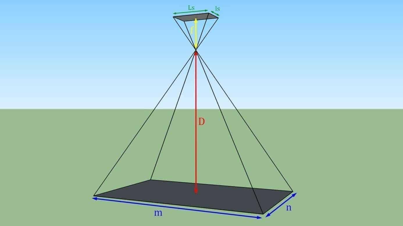
FIGURE 16: PROJECTION ON THE SOL OF A PHOTO TAKEN IN NADIRAL VIEW
Estimate flight height
The flight height will depend on the accuracy desired for the model. For this example, we will consider a useful precision of 15 cm over an area extending over an entire city. The calculation will be based on the camera in the nadial orientation. We will check with the slash cameras later (manufacturing of multi-camera systems usually build their systems so that the ground-based spatial resolution is substantially the same between the nadial and oblique shots).
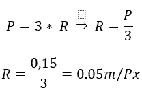
First of all, let's start by calculating the necessary ground spatial resolution.
Let us now calculate the ground surface to be covered by the photos to achieve this resolution:
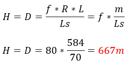
We can now calculate the corresponding flight height (for nadal views, the flight height H is equivalent to the distance to the subject):
(because the ratio between f and D is not significant, some simplifications are made in the formulae in the rest of the document).
Determination of flight plan and shooting frequency
The configuration of the flight line depends on the necessary overlap. In this example we will use a longitudinal overlap of 80% (CL) and a lateral overlap (cl) of 60% for photographs in nadiral mode (Figure 17).
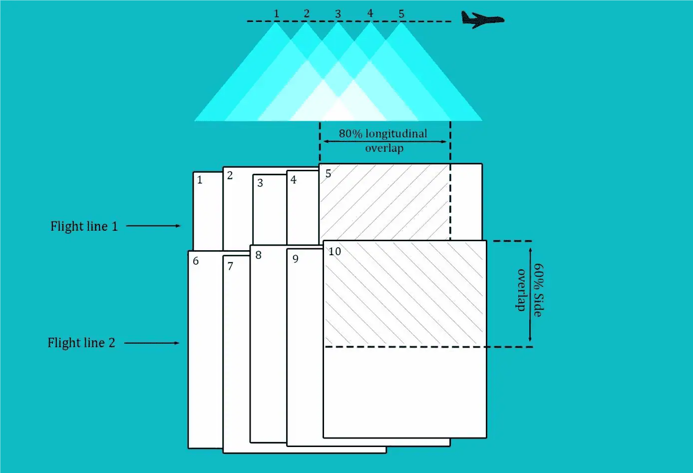
FIGURE 17: LONG-TERM AND LATERAL CHECKS
The distance between two consecutive photos in the same flight line is determined as follows:
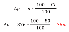
The distance between two flight lines is determined as follows:
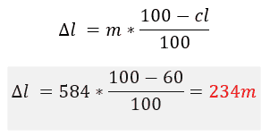
Checking the slash configuration
Ground Space Resolution : We will first determine the average distance from the sample to the ground. Due to the large vertical angle, the spatial resolution on the ground can be very different from one side of the photo.
We will consider the following: the oblique forward and backward shots are in a landscape orientation (Figure 18).
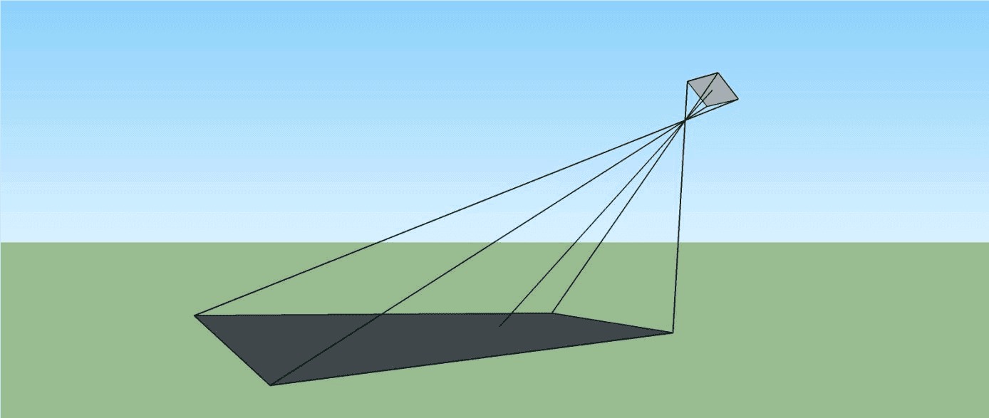
FIGURE 18: OBLICAL VIEW TAKEN AT LANDSAGE
We will first calculate the dimension n photo projected on the ground (Figure 18).
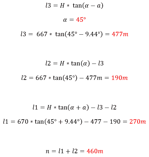
We first determine the angle a.
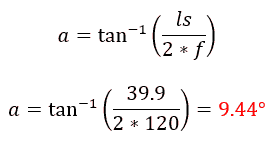
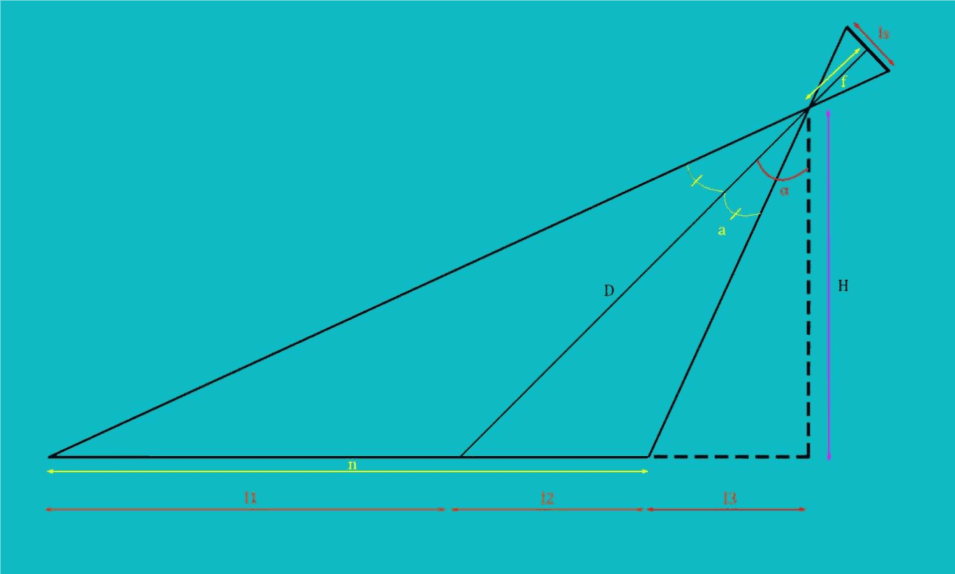
FIGURE 19: GEOMETRY
We can now calculate the dimensions l1, l2, l3 and n :
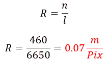
The mean ground spatial resolution is:
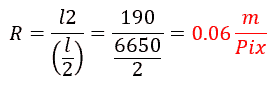
The ground spatial resolution for the back half of the photo is given by:
The ground spatial resolution for the front half of the photo is given by:
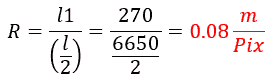
The results show that ground spatial resolution is fairly uniform for all cameras in the system.
Longitudinal recovery We can now check the longitudinal cover between two consecutive photos taken by the same slant camera (front or rear).
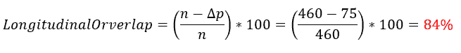
Lateral recovery : we can now check the side cover of two different flight lines between two photos taken by the same slash camera (front or rear).
We must first calculate D and m (Figure 19 and Figure 16):
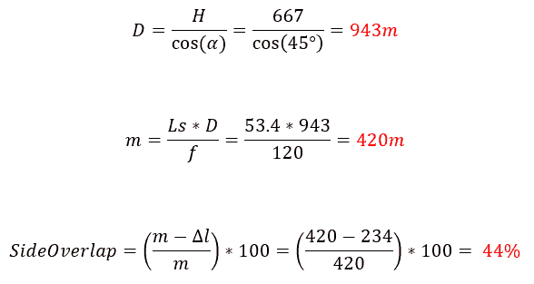
We can note that the lateral cover is a little weak. We could increase it by reducing the distance between flight lines. Anyway, ContextCapture is able to find matches between oblique photos and nadir, thus reducing the effect of this small lateral cover between oblique photos.
The same calculation can be used to estimate the overlap of other oblique cameras.
Conclusion
Depending on the subject, the desired accuracy, the purpose of 3D modelling, and the acquisition device, the acquisition method can be completely different from one project to another. Each scenario must be carefully studied before going to the field and starting acquisition. Otherwise, you will probably have important photos that will be missing and you will find yourself with incomplete or erroneous results.
This document is intended to show you good practices for different applications, the use of several types of devices whether they are portable, mounted on drones or even airborne.
Remember that the photo is the basis of all calculations.
The better the quality and spatial sampling of your photos, the better 3D reconstruction!